MDCtrl
The Development Process for Creating MDCtrl, Powered by Raspberry Pi Pico and GP2040-CE
DIY Simple and Portable Stickless Controller
Check Out The Github For The Files HERE, and quicker write up HERE
Note: I categorize this project as an early prototype of MDCtrl, and in the future, I hope to revisit this project and make Version 2 with a smaller board, a cleaner PCB design, and a better case. I’m open to any criticism and suggestions, feel free to start a discussion in the repo.
Introduction
What is MDCtrl?
MDCtrl is an Do It Yourself (DIY) portable controller that is made with the help of KiCad and Raspberry Pi Pico powered by GP2040-CE.
Reasons For This Project
I really want to try a stickless controller to play my games, but when I saw the price, I’m suprised by how expensive they are. So I thought “why not just make it myself, and make it open source so people can make it their own?. it should be cheaper and not that hard right?” (Oh, how wrong I was about this thought)
Bill of Materials (BOM)
The materials you need to make MDCtrl:
- MDCtrl PCB
- Raspberry Pi Pico
- 12 Hotswap Socket (Optional for hotswappable keyboard switches)
- 12 Keycaps
- 1 Stabilizer
- 5 6x6x5 Tactile Switches
- Soldering Components
Development Process
Development process includes several phases, from the initial concept to part assembly, here’s the list of phases in development process:
- Concept
- Layout
- PCB Design
- Part Assembly
1. Concept
In the realm of all button controller or some called it stickless controllers, price, availability, and repairability are common drawbacks compared to traditional stick controller. Even the budget-friendly stickless controller can be quite expensive, which discourages people who are simply curious about trying them out. With this in mind, MDCtrl aims to be more user-friendly, affordable, and open-source making it easier for people to experience stickless controller. If they enjoy the experience, they can then consider investing in a flagship stickless controller.
- Key Features:
- Affordable & DIY-Friendly
- MDCtrl is made to be cheaper than mainstream stickless controller and easier for people to make their own MDCtrl with just basic soldering and flashing knowledge
- Hotswappable Keyboard Switches
- MDCtrl uses hotswappable keyboard switches, so users can easily replace without soldering each keyboard switches.
- Portable & Space-Efficient
- MDCtrl compact size makes an ideal gaming on the go. It uses less space making it easy to carry on a trip or store it when not in use.
- Open-Source
- MDCtrl open-source design makes it easy for people to contribute, modified, and share their customized design and adapt the controller to fit personal taste.
- Affordable & DIY-Friendly
2. Layout
After the initial concept is done, now we need to determined how the layout of the buttons and component will be placed, I’ll be using jfedor flatbox and Hitbox Controller as a base and modify them.
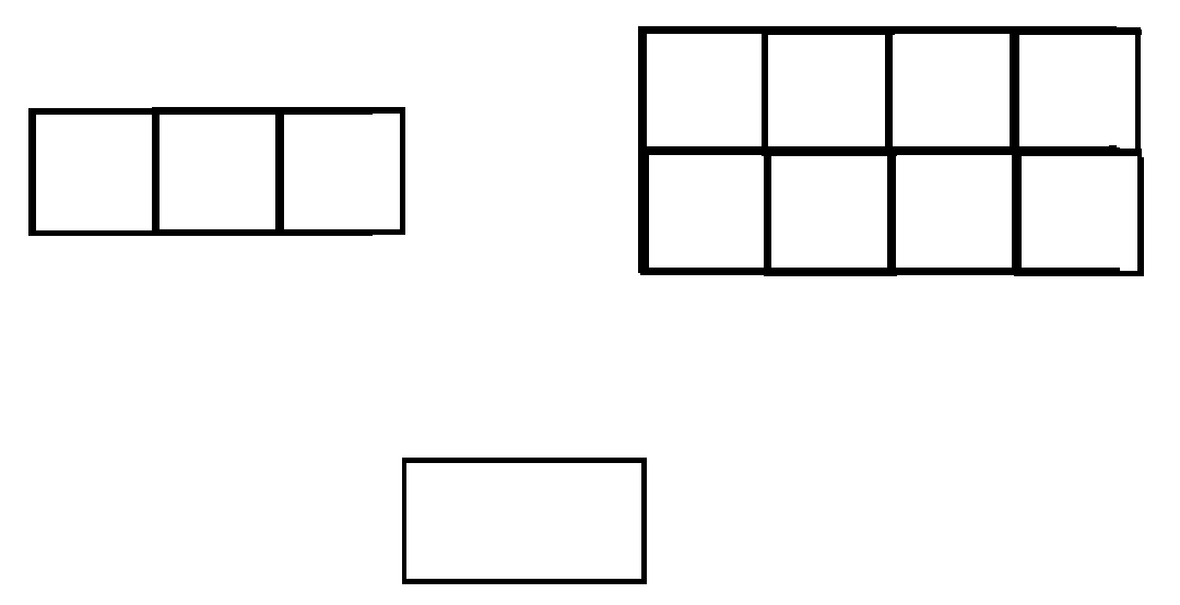
I started by drawing the layout in paint 😁 and then asked around the community about their thoughts on the initial design.
After getting their feedback, and confirming the layout by actually printing it out and testing the button placement, the initial MDCtrl layout felt cramped and uncomfortable. However after adjusting the button placement based on the community’s feedback, the resulting layout feels more natural, and comfortable to useAfter getting their feedback, and confirming the layout by actually printing it out and testing the button placement, the initial MDCtrl layout feels cramped and uncomfortable, after changing the button placement according to the feedback given by the community, the resulting layout feels more natural, and comfortable to press.
3. PCB Design
Before starting the PCB design phase, I would like to give a massive thank you to Noah Kiser for providing an excellent guide that I used to make this controller. You can check him out HERE or watch the spesific video I followed HERE
PCB Design Uses Firmware GP2040-CE Wiring, Raspberry Pi Pico Footprint by Nicolò Carandini, and Keyboard Switches Footprint
Creating a PCB Design involves two parts:
- Schematic Design
- PCB Layout Design
Schematic
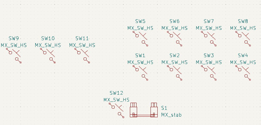
Schematic begins with placing down symbols that are needed to start building the controller. Early schematic design uses two symbols.
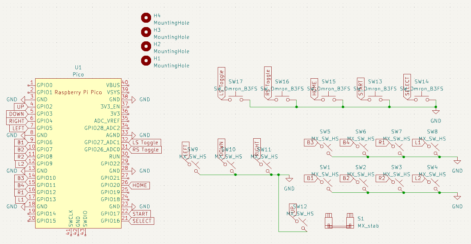
After several feedbacks and revision to accommodate the number of buttons needed for general use (beyond just arcade and fighting games), the final Schematic Design includes Raspberry Pi Pico Schematic by Nicolò Carandini, tactile switches, wiring, and mounting holes.
PCB Board Design
PCB Board Design begins after placing down symbols in the schematic and accessing Board Editor that you can find in KiCad with this icon.
After pressing Board Editor and updating the PCB from the schematic, the component will get imported and their connections. With the imported component, you can start designing the PCB by dragging them into place and defining board outline using Edge.Cuts layer to draw the outline of your PCB.
Now we need to route the traces to connect the components, this can be done manually by clicking on Route Tracks or automaticly using KiCad Interactive Router. With KiCad you can also see the 3D View of the PCB using 3D Viewer.
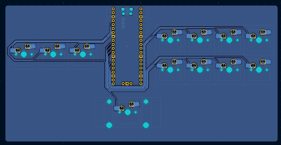
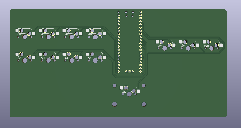 3D View Traced First PCB Design
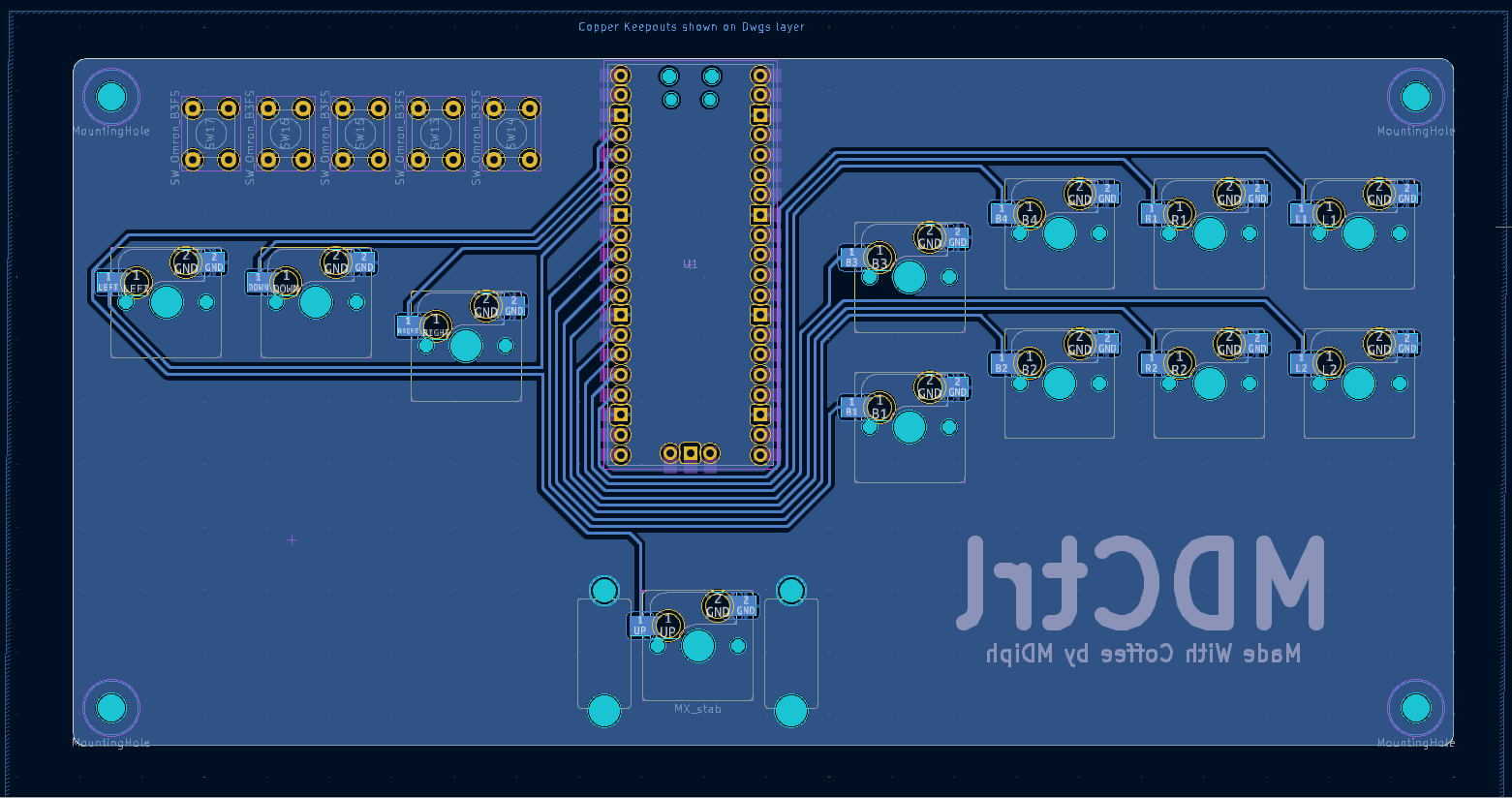
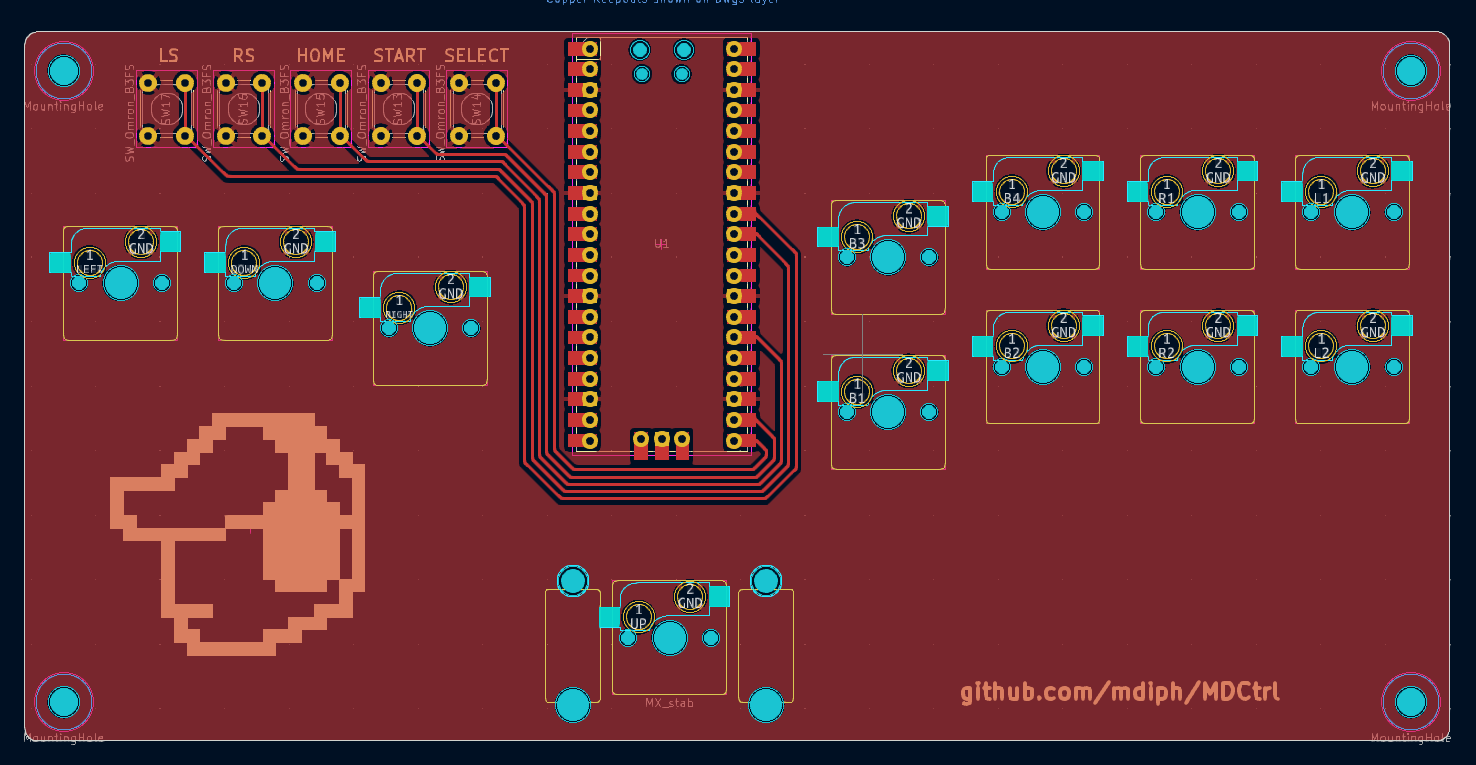
With the initial layout in mind, I moved some component to match the layout and added new elements based on community feedback such as customized silkscreen and tactile switches. The included image shows the front copper layer (colored red) and back copper layer(colored blue).
3D View MDCtrl PCB Design
4. Part Assembly
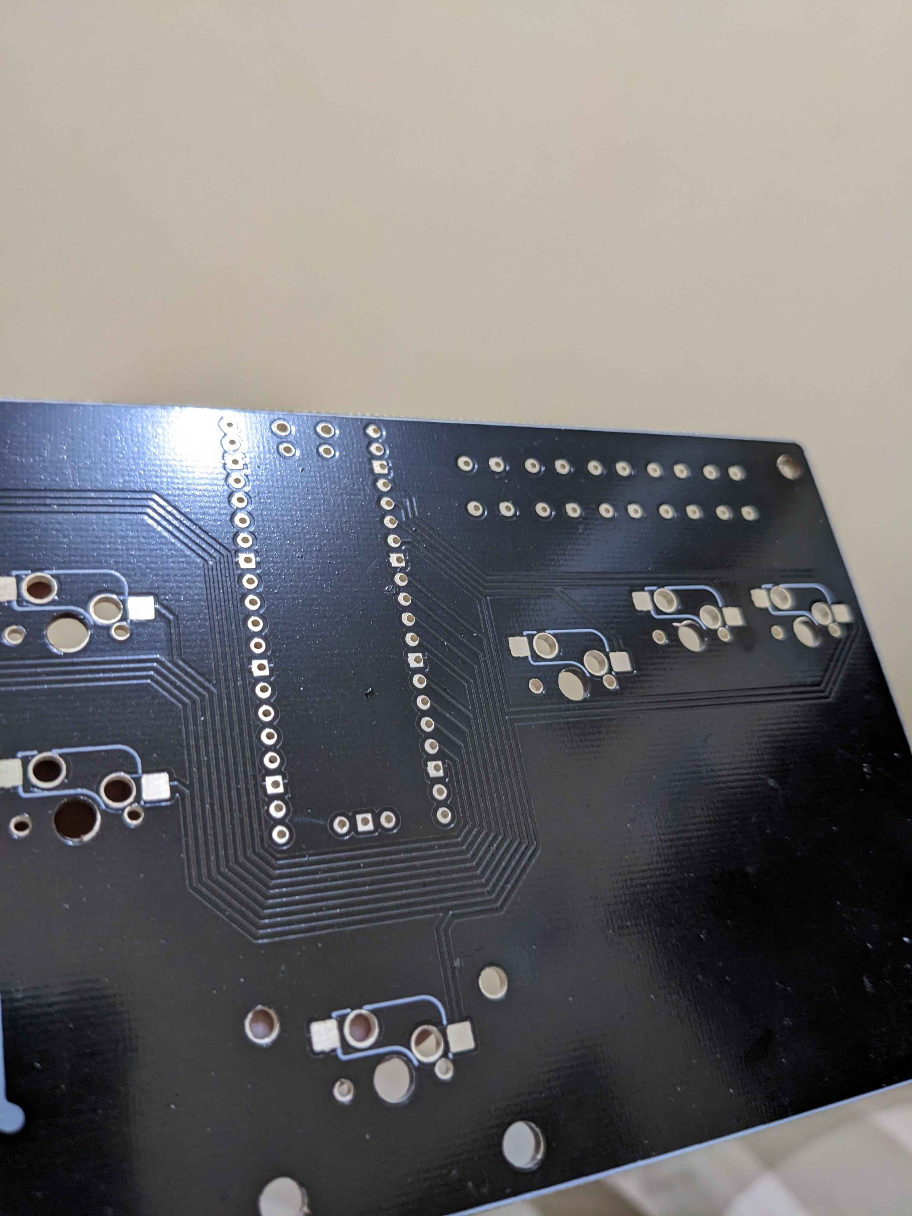
Part Assembly begins by ordering the PCB in a PCB manufacture by using Gerber that can be accessed by going to File -> Plot and make sure the file format is set to Gerber.
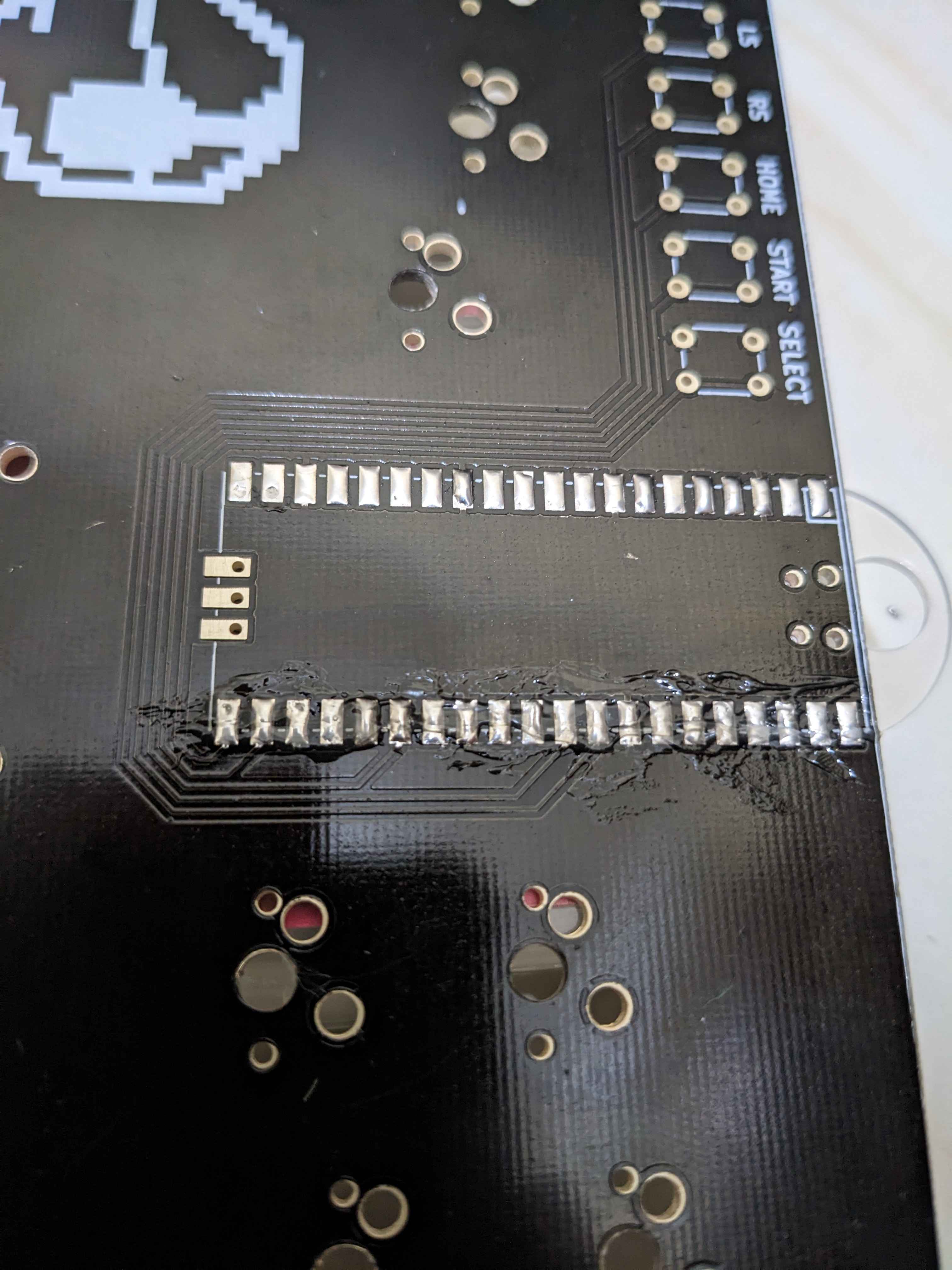
After the PCB arrived, we can begin soldering the component into the PCB board, the first component that I soldered is the Raspberry Pi Pico, begins by preparing the pad for the solder.
With the pad tinned, soldering the Raspberry Pi into the PCB becomes easier, just make sure after soldering, try to wiggle the Raspberry Pi to make sure you have a firm connection.
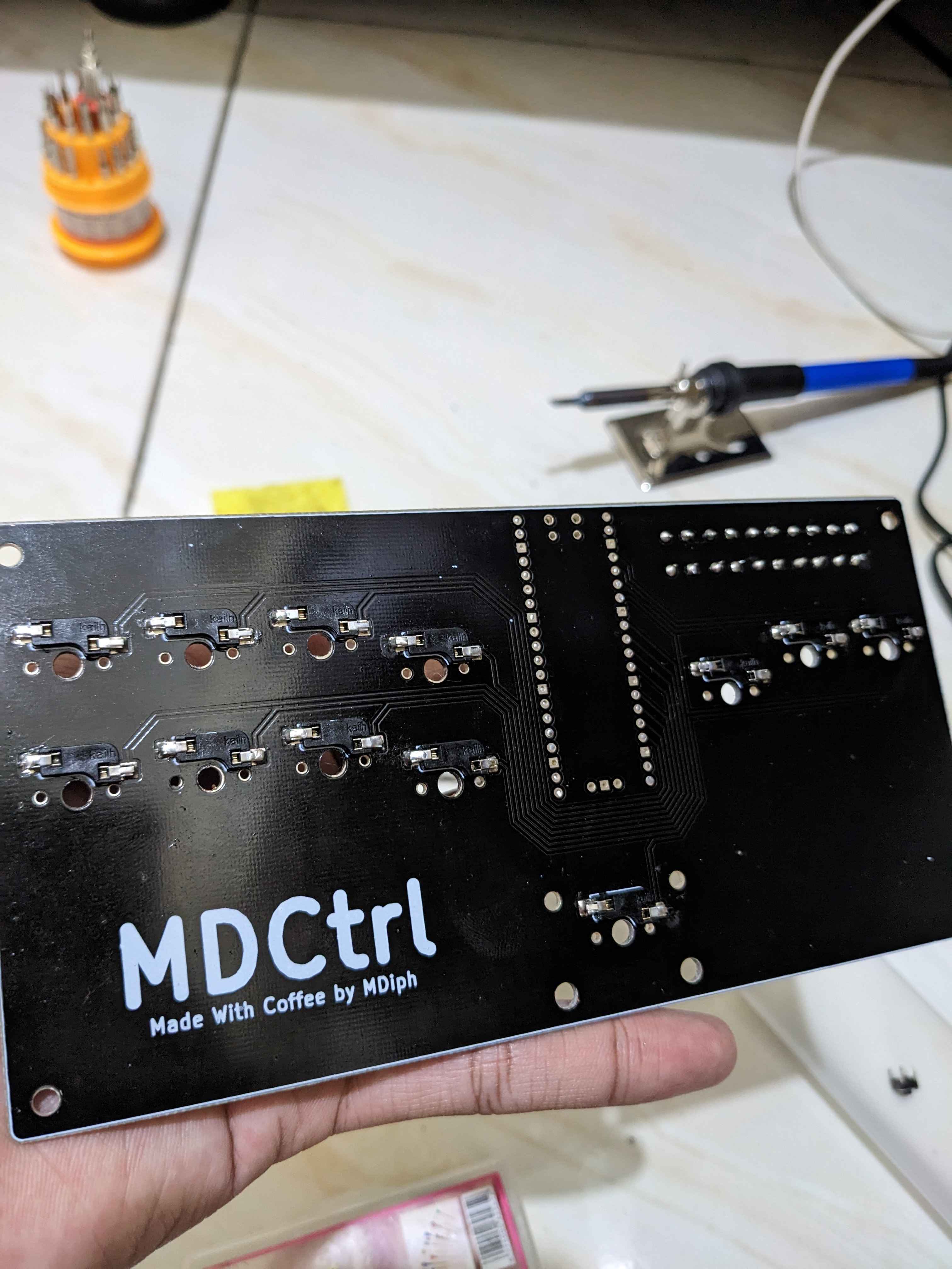
Now we can move into the other component, like hotswap socket and the tactile switches.
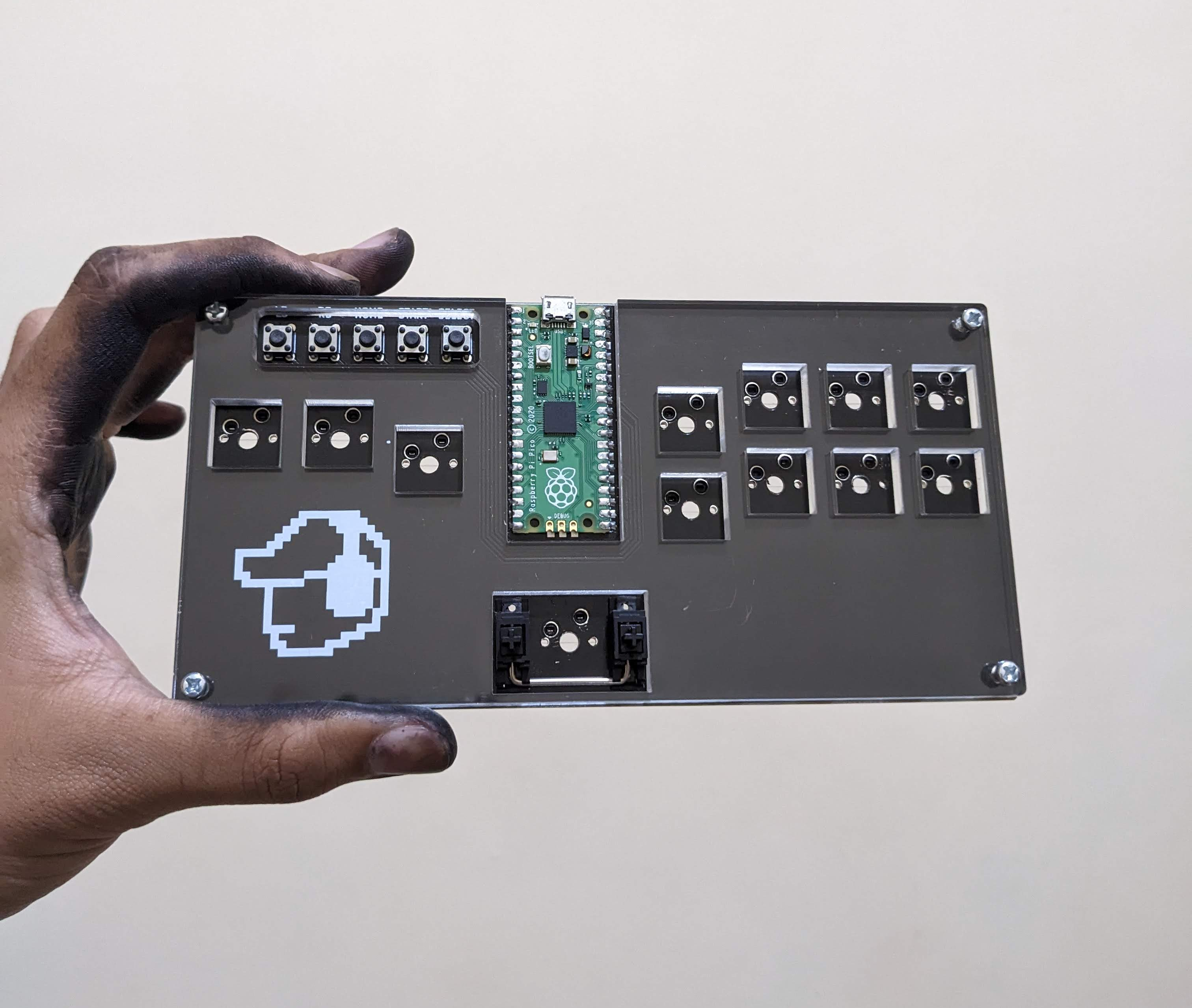
And that's it, the PCB for MDCtrl is done!, all we have to do now is flash the Raspberry Pi Pico with GP2040-CE.
Implementation
You can Check out the Firmware Installation for GP2040-CE from the official site HERE
Testing
After flashing the GP2040-CE firmware onto the Raspberry Pi Pico, you can verify if the MDCtrl is recognized as a controller by using Gamepad Tester
MDCtrl Testing
Challenges
This project is not as smooth sailing as it initially seemed. There are various challenges that arise while working on it:
- Difficulty in finding the right footprint for the keyboard key, hotswap socket, and Raspberry Pi Pico.
- Learning the PCB manufacturing process from schematic design to PCB layout.
- Limited specifications for PCB manufacturing due to constraints of local PCB fabrication tools.
- Navigating various communities to gain additional insights for the controller.
But thankfully I’ve learned a lot by working around and overcoming those challenges.
Future Improvements
There are a lot of things that can be improved on this MDCtrl project, from the use of other type of Raspberry Pi to make MDCtrl have even an smaller footprint, better PCB layout
Conclusion
Creating MDCtrl has been a wonderful journey, from learning the basics of PCB design to navigating various communities to gain more input for the controller. I hope to revisit this project in the near future and create a better version with newer parts.
Thank you for reading this write up! 👍
